
A Breif Guide To Wireless Local Area Networks
A Breif Guide To Wireless Local Area Networks
Alida Networks designs a Wireless Local Area Network an airport using Cisco Unified Wireless Solution Architecture.
Design Basis Memorandum
With a wide proliferation of advanced gadgets and wifi enabled devices a mobile user expects the same level of accessibility, security and quality as a wired user. He requires a 24×7 access to applications like, internet, central resources back at the office, email and web while on the move. Therefore, there’s a need to have a robust and secure wireless solution that not only allows users to access network resources from anywhere but also protects the network from unsolicited entries. Wireless, however, has some inherent shortcomings that make it really challenging for it to compete with its wired counterpart. Having these thoughts in mind, Cisco, came up with the Unified wireless framework that can not only make the wireless network highly secure but also makes it robust, resilient, available and hence a preferred means of network connectivity. From a high level standpoint, this framework transfers the intelligence from the access points to LAN controllers who are totally aware of the network and make and enforce policies across all the access points. On top of the controllers, there are wireless control systems that monitor and manage the entire wireless network. This framework therefore, offers central management and monitoring of the entire wireless network and is even capable of handling threats, risks and attacks from this centralised resource making the overall accessibility of the network highly secure. The below figure shows the logical positioning of some of the major components in unified wireless LAN solution.
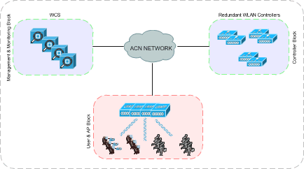
Figure 1 Unified Wireless Solution Architecture
The need to have such a design in an airport environment is no more a luxury but keeping the criticality of the network and the diversity of the users accessing this network in mind, it becomes a dire necessity to have such a hierarchical and secure network in place.
Detailed Functionality
Access to WLAN
In accordance with the specifications under standard procedures, airport staff will first go through an authentication mechanism and if authenticated will be dynamically positioned into a certain VLAN that will allow them to access resources relevant to that particular user. This functionality will be achieved using Cisco ISE in conjunction with IEEE 802.1x.
When the user tries to associate with a LAP (Light weight access point), it passes on the credentials to the ISE server for validation. Once the authentication is successful, the ISE will return certain attributes which will determine the VLAN ID of the user. The following diagram stipulates the whole process:
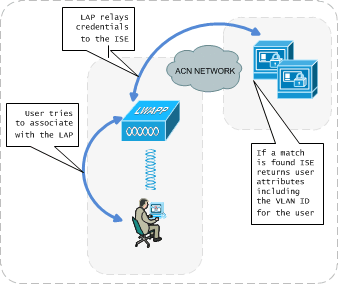
Figure 2: User Authentication
The ISE device (which is out of WLAN scope, but will only be discussed from a high level standpoint) is a one box user access security solution that contains different components like ACS (for AAA authentication) and the whole range of NAC functions like NAC profiler, NAC guest and NAC manager. The ACS component in ISE does authentication and authorisation based on user credentials. The NAC functions make sure that the user’s security is in compliance to the airports security policy. If all is fine, the user is given access to the wireless network, however, will only be able to access resources it is authorised to use.
Guest Access
As per the standard procedure requirements we have identified a need to allow guest users to the wireless network. These guest users will be able to access the wireless network without passing through any authentication mechanism, but will be allowed access to various resources in a walled garden approach. In this walled garden, the user will be open to some basic information of the airport and commercials from various shops/services in the airport. If the user opts he can buy internet access and by providing the credentials will be able to even connect to the internet.
The underlying technology behind the allowance of Guest access is through the use of a guest anchor wireless controller placed in the DMZ. All the guest traffic that comes to an internal WLC will be transparently tunnelled to the anchor controller placed in the unsecured area of the network. This mechanism safeguards the internal network from outside users who can potentially damage resources that are not meant for them.
In order to redirect all the guest traffic from the internal wireless controllers to the anchor controller an EoIP (Ethernet over IP) tunnel is established between them. It ensures that security and QoS policies can be separate, and are differentiated between guest traffic and corporate or internal traffic. Using this technique, all associated guest traffic can be transported transparently across the enterprise network to a guest anchor controller that resides in the unsecured network area. The below diagram depicts the above technique:
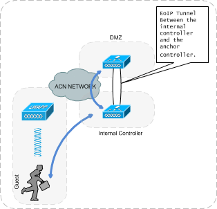
Figure 3: Guest Access
VoWLAN
Voice over Wireless LAN is one the most mission critical application that will be running on the airport wireless LAN network. It requires the WLAN to have best quality of service mechanisms and requires attributes like fault tolerance, critical traffic prioritization, very less end to end delay call admission control and a non-overloaded wireless network. We will ascertain the following points in the wireless design to make sure the airport staff can roam around with wireless IP Phones with the best possible voice quality:
- Access Point Overloading – The most important consideration for voice in a wireless environment is that wireless users don’t overload any access point. In case an access point is overloaded with too many users, the total bandwidth available to each user decreases as it’s inversely proportional to the number of active connections. Therefore, the access points will be positioned in such a way that each cell is being taken care of by more than one AP at any point in time. This design consideration is also in accordance with the Employer’s Requirement Document point 2.2-K (Document ‘AL-600-T-11103_Rev 01_Wireless_Local_Area_Network _17.09.2011’).
- Quality of Service – QoS is undoubtedly the most important mechanism to be deployed in the WLAN environment for this medium to support time and delay critical traffic like voice. The underlying idea behind this technique is to prioritize sensitive traffic over the traffic that can easily work in a best effort environment like http. In order to enforce this in the network we’ll be using 802.11e (Wireless Multimedia, IEEE standard) as all the proposed Cisco wireless components support this standard. QoS will be discussed in detail in one of the following sections below.
- RF Planning – The packet loss and jitter requirement of voice and the increased mobility of wireless handset users across the airport, places high demands on connection quality, coverage and user expectations that are way beyond the standard requirements for a data only deployment. Therefore, it is obvious that proper RF planning is the foundation of any successful VoWLAN deployment. We’ll be following the below guidelines as per the best practices in order to do proper RF planning for the wireless network at the airport:
- For the 2.4 Ghz network, the minimum cell overlap will be at least 20 percent as compared to standard data wireless network designs where the overlap can be from 5 to 10 percent. The minimum cell overlap for 5.8 Ghz will be approximately 15 to 20 percent.
- The cell boundary will be within -67dbm signal strength.
- Areas expected to have more than usual number of users, will be deployed with extra access points keeping in mind that as per the best practices, no more than 25 clients should connect to one access point.
- Roaming – Roaming is the ability for a wireless user to seamlessly move around the wireless network without worrying about losing connection if one moves out of the current cell boundary. Typically in an airport environment, the airport staff and the guests/passengers have to move around all the time with wireless handheld devices and therefore it has become really important to enable the network to allow this function across the airport. In a typical wireless deployment, a roaming action is triggered when the RSSI (received signal strength indicator) and SNR (signal to noise ratio) goes below the set minimum value, indicating that a client is at the boundary of the current cell and is trying to move out. From a technical perspective, roaming can be classified in two types – roaming between two access points registered to the same controller and roaming between two access points registered to different controllers. The roaming in a wireless network is handled by fast roaming algorithms which includes CCKM (Cisco centralized key management) and PTK (pairwise transient key). In our design all controllers will be assigned the same Mobility Group so that wireless clients can roam all over the Airport where there is a wireless connectivity to the access points
RF Interference Mitigation
Another challenge faced by the wireless technology today is that it shares the same frequency spectrum with most of the other devices working cordlessly. All these non-IP devices such as, Bluetooth devices and microwave, interfere with the wireless signals and can drastically deteriorate signals and lead to packet loss in the wireless network. Therefore, understanding this potential threat we will be deploying a spectrum expert that will work in conjunction with wireless LAN controllers and wireless control system to identify if there’s any interference in the wireless network and then directing the APs to change their channels accordingly for noise free transmissions.
Location Tracking
As part of the requirements set by the Employer’s Requirement Document, location tracking will be needed across the entire wireless network. In response to this requirement we have proposed the cisco mobility service engine, that will integrate with the wireless control system to provide location and more details of the wireless clients and WIFI enabled Tags around the wireless network. The Cisco Context-Aware Mobility solution will provide the ability to capture and integrate into airport operational processes, detailed contextual information about such things as location, temperature, and the availability of an asset. This integration with applications is fast becoming the next level of true enterprise mobility. With the Cisco Context-Aware Mobility solution, mobile users can go beyond anytime, anywhere connectivity to automatically having the right device, the right application, and the right environment while on the go. The Mobility Services Engine will provide:
- A Context-Aware Software that provides real-time network visibility and asset management for Wi-Fi clients, tagged assets, and wired devices. The airport administration will gain critical business intelligence to improve workflow, troubleshoot mobile clients, and quickly locate rogue devices and interferers.
- Adaptive Wireless Intrusion Prevention System (IPS) Software which detects and reports on the full range of 802.11 attacks, providing advanced forensics for threat analysis and prevention. With this the airport will be able to maintain constant awareness of their RF environment to minimize legal liability, protect brand reputation, and assure regulatory compliance-including PCI 2.0 standards.
With integrated location tracking, the wireless LANs will become much more valuable as a corporate asset for the airport. Airports network administrators, security personnel, users, asset owners and others will benefit from these location-based services which will allow them to achieve the following:
- They will be able to quickly and efficiently locate valuable assets and key personnel.
- They will be able to improve on productivity via effective asset and personnel allocation.
- They will be able to reduce loss because of the unauthorized removal of assets from airport premises.
- They will be able to improve on customer satisfaction by rapid location of critical service-impacting assets.
- They will be able to improve the WLAN planning and tuning capabilities.
- They will be able to coordinate Wi-Fi device location with security policy enforcement.
- They will be able to determine the location of rogue devices.
- They will be able to monitor health and status of key assets in their environment and receive prompt notification of any changes.
- They will be able to receive prompt notification when unauthorized addition or removal of assets occurs.
Non-Functional Specifications
High Availability & Redundancy
The availability of the wireless network can be measured from two different perspectives:
- Ability of the end users to failover to a redundant device in case there’s a failure.
- Ability of the network devices to be aware of each other’s presence and know when one of them is not available and consequently take appropriate actions.
From a design perspective, there’s no single point of failure in the wireless network. The network has been designed in a redundant fashion wherein all the critical equipments, assuring availability, have been doubled. So at any single point in time, even if there’s a failure on one device, its counterpart will be ready to take full load of the failed device. From the technology perspective, all the equipments proposed in the network supports active/active configurations and are intelligent enough to know if there’s a failure on the network and what actions to take in order to seamlessly keep providing services to the end users.
The following points discuss the availability at each layer of the wireless network:
- Entry Point: the entry level which will effectively be the access points have more than one AP covering each cell. So in case there’s an AP failure, the WLC directs the neighbouring AP to increase its signal power to cover the hole in the wireless coverage area. This ensures availability at the entry level.
- Controllers: the design assumes 1+1 redundancy on the controllers where for each controller there’s a provision for a redundant controller to take over in case of a failure.
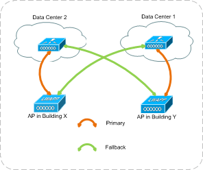
Figure 6: Controller Redundancy
Each proposed Wireless LAN Controller is licensed to handle 500 access points. As per the above diagram, the network will be designed in such a way that the access points in each building will have a primary WLC in the data center 1 and a secondary controller in data center 2. In case the primary fails the access points will be able to failover to the secondary controller.
This will not only offer availability on the controller level but will also make sure that the access points function, even if one complete data center fails. This design feature will allow the airport to have a fully operational system even in case of a failure.
The below diagram depicts the flow of data/management traffic to and from an access point if the primary controller that it had registered to has failed.
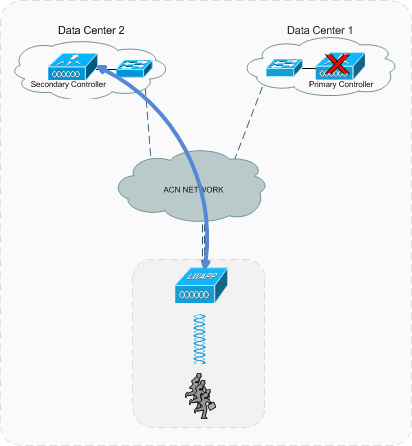
Figure 7: Controller Failover
As shown in the above diagram, the access point establishes a CAPWAP tunnel between itself and the secondary controller as the primary has failed. The above mechanism is important to understand from the data flow perspective, because the designers of the other system like ACN, and CNS should cater this sudden change in traffic flow into their proposed solutions.
One point to note here is that as mentioned before, since each controller can handle 500 access points it will have only 250 active APs registered to it and 250 APs will register only in case of a failure. So from a sizing perspective, controllers will be provided considering only 250 active APs per controller. It’s also important to note that under normal conditions each controller will only be utilized with 50% percent of the total capacity it can offer.
- ISE: the identity service engine that will allow wireless users to authenticate and have the end users comply with airport’s security policy will also be redundant ensuring 24×7 availability. The ISE is out of the scope of this system, further details can be found in the ACN high level design document.
Performance
The overall network performance and response time is driven by application requirements and amount of traffic on the links.
On the Radio Frequency side, the performance of the WLAN with respect to the clients depends on many factors like interference and high noise levels. A professional site survey must be conducted in order to determine the presence of interference and noise, and to optimize the placement of the APs.
The round trip time (RTT) of WLAN Controller to WLAN Controller IP connectivity (Mobility messages) is designed to be equal to or less than 10msec, and the RTT for WLAN controller to AP connection (Data & Control packets) is equal to or less than 100 msec.
In essence the wireless network is designed to perform well even when the network is highly loaded with multiple access points per cell and quality of service mechanisms for voice and video traffic.
Security
Wireless LANs are vulnerable to a wide range of active and passive attacks that may compromise the security and integrity of the network and data that traverses the network. The ability of an unauthorized intruder to monitor traffic, gain unauthorized access to resources, and deny the service of a wireless network are issues that must be considered. To help mitigate these risks, a strong wireless LAN security solution is recommended. An effective wireless client security solution consists of two (2) major elements: Authentication and Encryption.
Authentication serves the purpose of verifying that wireless LAN users are in fact valid users. If a user is not authenticated, they are denied access to the wireless network.
Encryption provides protection for traffic that travels over the wireless LAN infrastructure by changing the messages with a hashing algorithm so that they cannot be intercepted and/or altered by unauthorized parties who may be in the air space of the wireless communication.
The native authentication and encryption features available in the original IEEE 802.11 specifications are generally considered to be inadequate for enterprise-class wireless LAN security. As a result, the IEEE 802.11i standard has been developed to provide a framework for strong, standards-based wireless LAN security. This framework includes several authentication methodologies based on the IEEE 802.1X admission control standard which utilizes one of several upper-layer Extensible Authentication Protocols (EAP).
It is important to note that most, if not all, wireless devices will need to have driver and OS upgrades to get the latest, most stable software.
Encryption Standards
WPA uses Temporal Key Integrity Protocol (TKIP) for encryption, including Message Identity Check (MIC) and Per-Packet Keying (PPK) via Initialization Vector (IV) hashing and broadcast key rotation and 802.1X for authenticated key management.
WPA2 is based upon the ratified 802.11i standard, and uses AES CCMP encryption at its core. WPA2 provides a stronger encryption mechanism through AES, which is a requirement for some corporate and government users. TKIP, the encryption mechanism in WPA, relies on RC4 instead of Triple Data Encryption Standard (3DES), AES, or another encryption algorithm.
Authentication Methods
The Cisco Wireless Security Suite (CWSS) provides authentication based on IEEE 802.1X admission control standard utilizing an upper-layer Extensible Authentication Protocol (EAP). Several EAPs are available:
EAP-TLS – EAP Transport Layer Security uses pre-issued digital certificates to authenticate a user to the network. This requires certificates and PKI management on both RADIUS servers and WLAN clients.
PEAP – Protected EAP is a hybrid authentication protocol that creates a secured TLS tunnel between the WLAN user and the RADIUS server to authenticate the user to the network. This requires certificates and public key infrastructure (PKI) management only for the RADIUS servers, alleviating the effort to install and manage certificates on WLAN clients.
EAP-TTLS – EAP Tunnelled Transport Layer Security (EAP-TTLS). Similar to the PEAP method, it requires certificates and PKI management only for the RADIUS servers.
EAP-FAST – EAP Flexible Authentication with Secure Tunnelling is an authentication protocol that creates a secure tunnel without using certificates.
The key difference between each of these authentication options is summarized below.
| Capability / Requirement | EAP-TLS | PEAP-GTC | PEAP-MSCHAP | EAP-FAST |
|---|---|---|---|---|
| Single sign-on (MS DB) | No | No | Yes | Yes |
| Login scripts (MS DB) | No | No | Yes[1] | Yes |
| Password expiration (MS DB) | No | No | Yes | Yes |
| OS availability[2] | XP, 2000 | XP, 2000 | XP, 2000, CE | Vista (?) |
| ASD support | No | No | No | Yes |
| MS DB support | Yes | Yes | Yes | Yes |
| LDAP DB support | Yes | Yes | No | Yes[3] |
| OTP support | Yes | Yes | No | No |
| Off-line Dictionary attacks | No | No | No | No |
| Fast Secure Roaming (CCKM) | No | No | No | Yes |
| Local authentication | No | No | No | Yes |
| Server certificates | Yes | Yes | Yes | No |
| Client certificates | Yes | No | No | No |
| Deployment complexity | Very High | High | High | Medium |
| RADIUS server scalability | Very High | High | High | Medium |
Table 1 Extensible Authentication Protocol (EAP) Comparison
Each of these standards-based security solutions requires RADIUS-based authentication servers.
The selection of the most suitable authentication and encryption of solution depends on several factors including: the capabilities supported by the various wireless client support, corporate policy regarding data security and ease of providing support. For large deployments, it is not uncommon to run multiple security architectures to accommodate the differing requirements of various wireless clients, as follows:
802.11i (802.1x authentication + TKIP encryption) – WPA1/TKIP Enterprise
802.11i (802.1x authentication + AES encryption) – WPA2/AES Enterprise
802.11i (Pre-Shared key + TKIP encryption) – WPA1/TKIP Personal
802.11i (Pre-Shared key + AES encryption) – WPA2/AES Personal
The WLAN solution proposed is IEEE 802.11i ready. Wireless users will be placed in the appropriate VLAN according to their security profile (username and password, trusted device etc.).
Other Security Mechanisms
- Other security features will be enabled in the proposed Wireless LAN solution:
- Management Frame Protection (MFP): In 802.11, management frames such as (de)authentication, (dis)association, beacons, and probes are always unauthenticated and unencrypted. In other words, 802.11 management frames are always sent in an unsecured manner, unlike the data traffic, which are encrypted with protocols such as WPA, WPA2, or, at least, WEP, and so forth.
- This allows an attacker to spoof a management frame from the AP to attack a client that is associated to an AP.
- When management frame protection is enabled, AP adds message integrity check information element (MIC IE) to each management frame it transmits. Any attempt to copy, alter, or replay the frame invalidates the MIC. An AP, which is configured to validate MFP frames receives a frame with invalid MIC, reports it to the WLC.
- Only the guest SSID will be broadcasted by the access points. All other SSIDs will be hidden.
- Over the air management will be disabled.
- The Cisco 5508 has inline intrusion prevention system that detects common attack signatures and since all management/data traffic will pass the controller it will work as an inline IPS for all wireless traffic.
- The Cisco WLAN has the ability to blacklist certain users or devices.
- Rogue access points can be detected and contained using the Cisco WLAN products proposed.
- Peer-to-peer traffic on the data networks can be blocked to avoid direct attacks from one device to another. Traffic from a client is always directed upstream to the controllers where it is protected by the infrastructure and the devices.
Recovery
Mean Time To Repair/Recover (MTTR) is the time taken to repair a failed hardware component/device. In an operational system, repair generally means replacing the hardware component/device. Thus hardware MTTR could be viewed as mean time to replace a failed hardware. The Mean time to recover however, is the time it takes to restore a failed function/system in the network.
The MTTR for a failed Wireless LAN Controller is as follows:
When the primary controller fails, the AP waits for the heartbeat time set, which is 30 seconds by default, to detect the failure of the primary WLC. After this period of time, the AP sends heartbeat messages seven more times, one per second, in efforts to find the primary WLC. If the AP does not hear from the primary WLC, the AP registers to an available WLC via the default process, which will be explained in ‘Traffic Flow’ section of this document under ‘Access Points & Wireless LAN Controllers’. Therefore, the process to detect the primary WLC failure and register to the secondary WLC takes approximately 50 to 80 seconds. Once the access point joins the secondary controller, it continues to send the discovery request to the primary controller in order to determine if the primary controller is back in operation.
As per the Smartnet (Warranty) Agreement, 20% of the spare will be available to address any hardware failure in the wireless LAN network. The MTTR after the Smartnet period expires will depend on the service level agreement that airport decides to have with the Operations and Maintenance contractor.
MTTR for a software module can be computed as the time taken to reboot after a software fault is detected. Thus software MTTR could be viewed as the mean time to reboot after a software fault has been detected.
MTTR for software depends on several factors:
- Software fault tolerance techniques used
- OS selected (does the OS allow independent application reboot)
- Code image downloading techniques
Depending on software fault recovery mechanism and reboot mechanism, this can be as low as 30 seconds to as high as hardware MTTR when software failure detection is not supported.
Reliability
The following table lists the predicted Mean Time Between Failures values for the different products in the proposed Wireless LAN Solution:
| Device | Predicted MTBF (in hours) |
| Cisco 1260 Series Access Point | 328,662 |
| Cisco 1520 Series Access Point | 191,849 |
| Cisco 5508 Wireless LAN Controller | 147,433 |
| Cisco 3350 Mobility Services Engine | 191,046 |
Table 2 MTBF Values for WLAN Devices
Manageability and Reporting
Simple Network Management Protocol
The use of SNMP to collect management data is essential to running IP network effectively. The Cisco Wireless Control System relies primarily on SNMP for the communication with the Wireless LAN controllers
SNMP v3 or v2c will be used where possible, is supported.
Logging
Logging of events on a network is an important part of any network security policy. The logging of events assists problem troubleshooting and security investigations.
Wireless Network devices can be configured to forward Syslog messages to Syslog servers.
Secure access with SSH and HTTPS
SSH and HTTPS will be enabled on the Cisco Wireless LAN Controllers while telnet and HTTP will be disabled.
The Cisco Wireless Control System will only be accessible through HTTPS.
CLI Management Authentication & Logging (AAA)
It is strongly advised to utilize either TACACS+ or RADIUS to authenticate users accessing network equipment. In addition, accounting may be used to keep a record of each command entered by a user. It is understood that customer will use Cisco Access Registrar with Radius.
Out-of-band Management
It is recommended that the management for all devices in the network should be performed via console access to the devices and through a dedicated out–of-band management network. This separates the management traffic plane from the data traffic plane on the network.
Data Flow and Data level architecture
All the traffic flowing from or to wireless client devices, is transported on the network through CAPWAP tunnels regardless if it is a normal or guest user.
All the CAPWAP traffic will flow from the Access Points to the Access Points’ primary controller through a separate VRF. Traffic will be decapsulated on the controller and be directed to the corresponding user VRF, depending on the security policy.
Two types of data flows exist, depending on the user type
-
- Normal User
- Guest User
For a normal user, the traffic is subsequently switched to the wired infrastructure and traffic is routed to its destination.
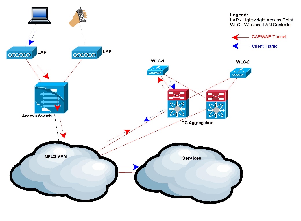
Figure 8: Normal User Traffic Flow
A guest user’s traffic flows through a CAPWAP tunnel from the Access Point to the AP’s primary controller. When the traffic reaches the primary WLC, an Ethernet over IP tunnel is formed between the primary controller and the Anchor controller. The guest traffic is decapsulated on the anchor and re-routed to its destination.
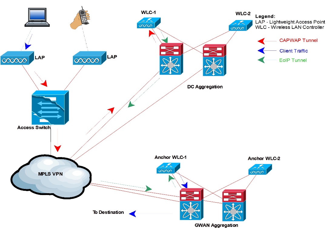
Figure 9: Guest User Traffic Flow
The data/traffic flow for both management and data traffic in the wireless network can be broken down into the following communication channels:
- Wireless Client (which can be anything from a wireless IP phone to a laptop or a smart phone with wireless capability) and the Access point.
- Access point and the wireless LAN controller.
- Wireless LAN controller and the Identity service engine.
- All the wireless LAN controllers and the wireless control system.
These traffic flows, the amount of data they will be carrying and protocols and all related details are discussed below:
Client and Access Point
Access Point choice is done on the machine radio of the client. Based on the manufacturer, driver, type of card, and so forth, it can use different metrics to make the choice. The most common AP affiliation mechanism used in most clients is based on signal strength received by the client from the APs. The 802.11 standard requires only that the wireless client card reports signal strength with a simple metric called Received Signal Strength Indicator (RSSI). So based on this indicator, once the machine’s radio has decided which radio to associate with, it sends AP join request to the access point. Once the AP receives this request it starts the authentication process to know if this client is allowed to access the wireless network and which resources and applications will it be permitted to access.

Figure 10: User AP Communication
The EAP methods to authenticate users will be defined in the Low Level design documents.
Access Point & Wireless LAN Controller
In the proposed unified wireless architecture, all the access points are controlled and managed by wireless LAN controllers. Each access point, in our design will associate to a primary controller and in case of a failure will be able to associate with a secondary controller. Once the AP associates with a controller a CAPWAP tunnel is created between the AP and the controller and all the data and management traffic is passed through the tunnel. The below set of sequence will occur in order for an AP to register to a controller:
- The LAPs issue a DHCP discovery request to get an IP address, unless it has previously had a static IP address configured.
- The LAP sends CAPWAP discovery request messages to the WLCs. The discovery request message is sent in the following sequence:
-
- If Layer 2 CAPWAP mode is supported on the LAP, the LAP broadcasts a CAPWAP discovery message in a Layer 2 CAPWAP frame. Any WLC that is connected to the network and that is configured for Layer 2 CAPWAP mode responds with a Layer 2 discovery response. If the LAP does not support Layer 2 mode, or if the WLC or the LAP fails to receive a CAPWAP discovery response to the Layer 2 CAPWAP discovery message broadcast, the LAP proceeds to step ii.
- If the LAP or the WLC does not support Layer 2 CAPWAP mode, the LAP attempts a Layer 3 CAPWAP WLC discovery.
- If step ii fails, the LAP resets and returns to step i.
-
- Any WLC that receives the CAPWAP discovery request responds with a CAPWAP discovery response message.
- From the CAPWAP discovery responses that the LAP receives, the LAP selects a WLC to join.
- The LAP then sends a CAPWAP join request to the WLC and expects a CAPWAP join response.
- The WLC validates the LAP and then sends a CAPWAP join response to the LAP.
- The LAP validates the WLC, which completes the discovery and join process. The CAPWAP join process includes mutual authentication and encryption key derivation, which is used to secure the join process and future CAPWAP control messages.
- The LAP registers with the controller.
The below diagram depicts the above process:
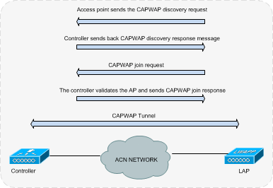
Figure 11: Traffic flow between controller & LAP
Once the LAP is associated with a controller a CAPWAP tunnel is established between them which transports all data and management traffic between the LAP and controller.
SYSTEM DESIGN
System architecture and description
Overall Network Architecture
The Centralized Wireless Network is the industry’s only unified wired and wireless solution that increases productivity and enhances collaboration, while addressing the security, deployment, management, and control issues facing large-scale WLAN roll-out, like the one we are going to deploy in Muscat International Airport.
Designed as a multiservice solution, the Centralized Wireless Network supports general Wi-Fi-enabled business applications like e-mail and Internet access and also supports specialized applications like mobile, inventory management, retail point-of-sale, video surveillance, and asset tracking. In addition to these data-oriented applications, airport management staff will be able to roll out the following services: guest access, voice over WLAN, rogue detection, and wireless intrusion detection and prevention. The below diagram depicts the high level design of the entire wireless network that will be deployed in the airport:
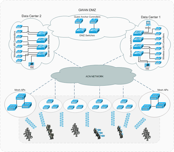
Figure 12: Wireless Network High Level Design
Summary
With a wide proliferation of advanced gadgets and wifi enabled devices a mobile user expects the same level of accessibility, security and quality as a wired user. He requires a 24×7 access to applications like, internet, central resources back at the office, email and web while on the move. Therefore, there’s a need to have a robust and secure wireless solution that not only allows users to access network resources from anywhere but also protects the network from unsolicited entries. Wireless, however, has some inherent shortcomings that make it really challenging for it to compete with its wired counterpart. Having these thoughts in mind, Cisco, came up with the Unified wireless framework that can not only make the wireless network highly secure but also makes it robust, resilient, available and hence a preferred means of network connectivity.
Cisco delivers a complete end to end Unified Wireless Solution Architecture that addresses all the above inherent issues with Wireless and hence delivers a best of breed and reliable wireless connectivity to both internal employees and guests at the same time.
- Requires machine authentication (machine accounts on Microsoft AD). ↑
- Greater Operating System coverage is available from Cisco Secure Services Client (CSSC) supplicant. ↑
- LDAP DB supported via manual (i.e. out-of-band) provisioning only. ↑